| Home |
| NOTE: | This procedure was written specifically for IBM 5150/5155/5160's. For clones, applicability/suitability will depend on how close the clone is of the IBM 5150/5155/5160 (including BIOS). For clones, references here to specific capacitors (e.g. 'C56') will definately not apply. |

![]() |
When attaching the 2 plugs (P8 and P9) from the power supply to the motherboard, ensure that you do that correctly, because it is possible (with force) to attach them to the wrong receptacles (i.e. P8/P9 swapped). 
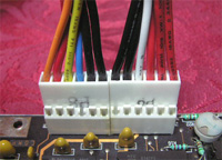
In the photo at the left, I am using a non-IBM power supply. And per here, because it has a red wire next to the orange wire, it means that the power supply is AT-class. If you are also using an AT-class power supply instead of an PC/XT-class one, then click here for details of a possible problem of using an AT-class power supply for this procedure. Note too, that non-IBM power supplies may use wire colours that are different to those shown here. |
![]() |
As specified earlier, on the motherboard, switches 5 and 6 on switch block SW1 are both to be set to the OFF position (monochrome card). For this procedure, that is very important - See note 1 below. Your SW1 switch block may contain different looking switches. If so, refer to here if you are unsure about what is on and what is off. |
![]() |
When connecting the speaker, the speaker's two wires need to go to the outer two pins of the 51xx motherboard's 4-pin speaker connector. Polarity is not important here; it does not matter which wire goes to which outer pin. (reason) (Some clone motherboards may use different pins, or may even use a different connector.) |
| Note 1 | Setting one switch to OFF and the other to ON, results in the CGA setting. In that case, if both switches are functional, and the switch reading circuitry is also functional, then {1 long beep, then 2 short beeps} will occur. However, setting both switches to OFF caters for one of the following possiblities: - Switch 5 in SW1 is set to ON, and switch 6 if set to OFF, but switch 6 is faulty in a way that results in it always being read as ON; or - Switch 6 in SW1 is set to ON, and switch 5 if set to OFF, but switch 5 is faulty in a way that results in it always being read as ON; or - Switch 5 in SW1 is set to ON, and switch 6 if set to OFF, but faulty switch reading circuitry is reading switch 6 as ON; or - Switch 6 in SW1 is set to ON, and switch 5 if set to OFF, but faulty switch reading circuitry is reading switch 5 as ON. |