Home 
under_construction.gif

IBM 5150/5155/5160 - Faulty motherboard symptom


NOTE:  

NOTE:  


This procedure was written for the IBM 5150 motherboard and the IBM 5160 motherboard.

The IBM 5155 contains an early 5160 motherboard, so treat the 5155 motherboard as a 5160 motherboard.


You are here because all of the following are true:
- You have an IBM 5150 or IBM 5155 or IBM 5160; and
- The fan in the power supply IS turning; and
- When you ran the 'minimum diagnostic test' procedure at here, you did not hear the expected beeps; and
- When you ran the 'minimum diagnostic test' procedure at here, at the part where you measure the +5V, -5V, +12V, -12V, and POWER GOOD, all of those were measured to be present and within tolerance.

Because all of the above are true, we know that:
- The IBM 5150/5155/5160's motherboard is not faulty in a way that overloads the power supply; and
- The power supply is not underloaded.
- An ISA card is not faulty in a way that stops the motherboard from executing the motherboard's BIOS ROM.


Preface

Ideally, I would provide a procedure that, using suitable test equipment, would lead you to the fault on your motherboard.

If that sounds simple to you, then it would inform me that you are completely unaware of the complexities of a motherboard.  Pretty much, any component (or PCB trace) could be faulty.  A procedure to logically diagnose a fault down to component level on a 5150/5160 motherboard could be many hundreds of pages long.  I am not going to create such a procedure.  Instead, below, I will take you through some common problems, and some things that are relatively easy to check.


Important

In the following text, you will see the term 'known-good' appear often.  It is important that everything you use to diagnose the motherboard is proven as working.
• For example, if you buy a replacement 8088 CPU online, maybe that CPU is faulty, or not even an 8088 (i.e. rebadged something else).  So, what you could be doing is removing a working 8088 CPU and putting a faulty/bad CPU in its place.
• For example, if you create for yourself, a Rudd's Diagnostic ROM, maybe you did that wrong.


Step 1 of 11  -  Visual inspection

Perform a thorough visual inspection of the motherboard.  You may spot a problem.  Use a magnifying glass.

Of particular note is the physical integrity of the trimmer capacitor.  There have been a few reported cases of a physically broken one.  Of note, is that a physically broken one may still be working fine (electrically).
IBM 5150 motherboard: Trimmer capacitor T1.
IBM 5160 motherboard: Trimmer capacitor C1.

See here for some examples of problem causes that I have spotted visually.

In the example at here, the 8088 CPU chip was found to be sitting in the math co-processor (NPU) socket, not the CPU socket.


Step 2 of 11  -  Socketed chips - General

Various chips on the motherboard are in IC sockets.

Try re-seating the socketed chips, in case there is a poor connection between a chip and its socket.  If in the re-seating process, you decide to fully remove the chip from its socket, then when putting the chip back in, ensure that you do not accidentally bend a pin up underneath the chip.
   
Are the socketed chips plugged in the correct orientation?  (If found, note that the chip may have been damaged by its wrong-orientation fitment.)
   
If you have access to known-good replacement chips, try swapping those into the sockets.
   
If you acquired the motherboard in a faulty state, then consider the possibility of incorrect chips (i.e. bad attempted repair).  An incompatible RAM chip is an example.


Step 3 of 11  -  Socketed chips - Remove unnecessary ones

Some (as listed immediately below) of the socketed chips are not required in order for IBM's motherboard BIOS to start and display something on-screen.  And so, in case one of those chips is the problem cause, remove them, and then see if the computer starts.

If present, remove the 8087 math co-processor chip (an optional chip).  After removal, set switch 2 in switch block SW1 to the ON position.  The 40-pin socket for the 8087 is adjacent to the socket for the 8088 CPU chip.
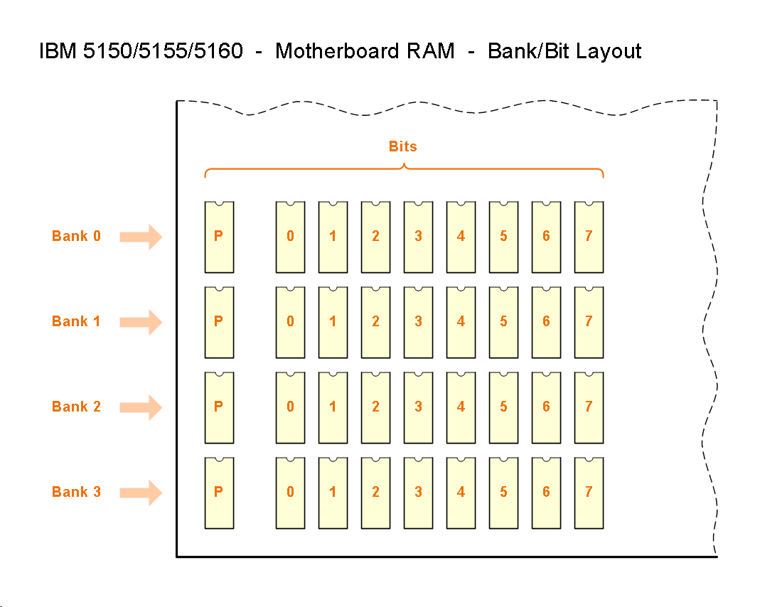
   
For something to appear on-screen, IBM's motherboard BIOS ROM only requires RAM bank 0 to be populated.  Therefore, remove the RAM chips from RAM banks 1, 2, and 3 - see here.  After doing that, in the case of the IBM 5155/5160, also set the two relevant switches in switch block SW1 for 'enable bank 0 only' operation.
   
Note that unlike IBM's motherboard BIOS ROM, Ruud's diagnostic ROM and the Supersoft/Landmark diagnostic ROM do not require RAM bank 0 to be populated.  (To see something on-screen.)
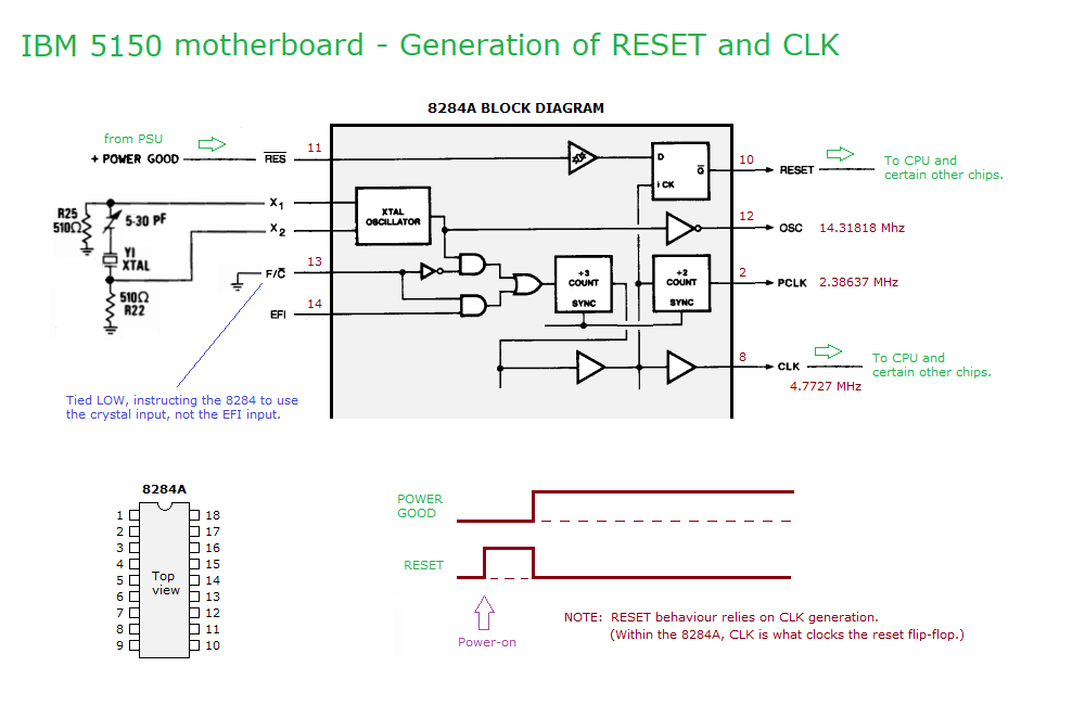
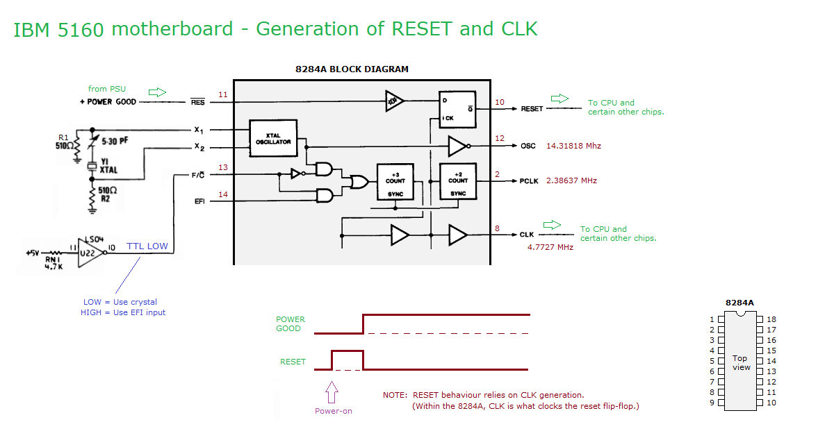

Step 4 of 11  -  Faulty motherboard BIOS ROM ?

Sometimes, the motherboard BIOS ROM chip/s is faulty. Consider acquiring a known-good replacement.

IBM 5150:  One chip, being U33.  See here.
IBM 5160:  Two chips, being U18 and U19.  See here.

Even if the motherboard BIOS ROM chip/s is not the problem, I think that having spares is a good idea.

And if acquiring a motherboard BIOS ROM chip/s, the supplier may also be able to supply you with a suitable Ruud's diagnostic ROM and a suitable Supersoft/Landmark diagnostic ROM.


Step 5 of 11  -  Faulty power supply ?

Even though the +5V, -5V, +12V, -12V, POWER GOOD, from the power supply all measured good, that is not a 100% check of the power supply.

There needs to be an adequte delay between the production of the +5V and the production of the POWER GOOD signal, otherwise the motherboard will not start.  An example of the delay in a particular power supply is shown at here.  In the IBM 5150 and 5160, the minumum allowable delay is 840 ns.

If you do not have the means to measure the delay for your power supply, then try a known-good power supply.


Step 6 of 11  -  Verify 4.77 MHz clock

Per here, the 8284A chip generates a 4.77 MHz clock on its CLK pin, pin 8.  It is critical that the 8088 CPU and 8288A chip and 8237 chip receive that.

Verify the presence of a clock on pin 8 of the 8284A chip.
- Ideally, you would use an oscilloscope, of adequate bandwidth, to do that.
- The next best tool is a logic probe, of adequate bandwidth, and with that, expect it to indicate pulses/activity.

An unreliable method is to use a multimeter in 'DC voltage' mode.  In that mode, the multimeter may read the average voltage of the clock signal.  You can see at here, that I, using a professional grade multimeter, measured about 1.8V on one of my motherboards.  Perhaps expect between 1.5V and 2V.  I cannot stress enough how unreliable this method is.  Your multimeter may not be able to do this.  Consider acquiring a logic probe (and the knowledge of how to use it).

Obviously, if the 8284A chip is not generating a 4.77 MHz clock, then you need to establish why that is.  A related diagram is at here, plus see note 1 below.

If the 8284A chip is generating a 4.77 MHz clock, then check that it is reaching the following pins of the following three chips:
•  Pin 19 of the 8088 CPU chip - see here.
•  Pin 2 of the 8288A chip - see here.
•  Pin 12 of the 8237 chip - see here.


Step 7 of 11  -  RESET signal to CPU

You reached this step because you verified that a 4.77 MHz clock is being generated (plus it is reaching the 8088, 8288A, and 8237 chips).

What we will do now is verify that the 8284A chip is not holding the 8088 CPU in a reset state.  For info, step 6 is a prerequisite for this step, because the 8284A chip requires itself to be generating the clock (internally) in order for its proper generation of the signal sent to the CPU's RESET pin.

Use a logic probe to measure the TTL logic state of the reset pin (pin 21) on the 8088 CPU.

Result:  If you measure a logic LOW (what is expected), then proceed to step 8.

Result:  If you measure a logic HIGH, then something is wrong related to the circuitry (8284A chip plus other things) that generates the RESET signal.  Go investigate that; see note 1 below.


Step 8 of 11  -  READY signal to CPU

You reached this step because all steps/checks up to this point are as expected.

The 8088 CPU can be instructed to pause/wait via a signal sent to its READY pin from the 8284A chip.  We will now verify that the CPU is not being instructed to to pause/wait.

Use a logic probe to measure the TTL logic state of the ready pin (pin 22) on the 8088 CPU.

Result:  If you measure a logic HIGH (what is expected), then proceed to step 9.

Result:  If you do NOT measure a logic HIGH, then something is wrong related to the circuitry (8284A chip plus other things) that generates the READY signal.  Go investigate that.


Step 9 of 11  -  8253 chip - Pulses out of channel #1

Going forward, an oscilloscope is required.  A logic probe is not adequate for this task.

See if your oscilloscope reveals pulses (of expected frequency, width, polarity) on pin 13 of the 8253 chip, per the diagram at here.

Result: Expected pulses present

For the IBM 5150 motherboard, the presence of pulses (of expected frequency, width, polarity) indicates that:
- The POST within IBM's motherboard BIOS ROM is being executed; and
- The POST within IBM's motherboard BIOS ROM has progressed to at least step 9 at here.

For the IBM 5160 motherboard, the presence of pulses (of expected frequency, width, polarity) indicates that:
- The POST within IBM's motherboard BIOS ROM is being executed; and
- The POST within IBM's motherboard BIOS ROM has progressed to at least step 13 at here.

Looking good so far.  Proceed to step 10.

Result: No pulses

If there are no pulses on pin 13 of the 8253 chip, or what is seen is not as expected, then the possibilties are:
- The POST within IBM's motherboard BIOS ROM is not being executed; or
- The POST within IBM's motherboard BIOS ROM is being executed, but a very early test is failing (resulting in the CPU being halted).

You could try the procedure at here to see if IBM's motherboard BIOS ROM is being executed.

You could also try a suitable Ruud's diagnostic ROM or a suitable Supersoft/Landmark diagnostic ROM.


Step 10 of 11  -  8253 chip - Square wave out of channel #0

You reached this step because all steps/checks up to this point are as expected.  We know that the motherboard BIOS ROM is being executed, and is progressing to a certain point.  We will now see if execution is reaching another certain point.

Now, see if your oscilloscope reveals a square wave on pin 10 of the 8253 chip, per the diagram at here.

Result: Square wave present

For the IBM 5150 motherboard, the presence of a square wave (of expected frequency) indicates that:
- The POST within IBM's motherboard BIOS ROM is being executed; and
- The POST within IBM's motherboard BIOS ROM sucessfully tested the first 16 KB of RAM; and     (Step 13 at here.)
- The POST within IBM's motherboard BIOS ROM has progressed to at least step 19 at here.

For the IBM 5160 motherboard that has a 1982 dated BIOS ROM fitted, the presence of a square wave (of expected frequency) indicates that:
- The POST within IBM's motherboard BIOS ROM is being executed; and
- The POST within IBM's motherboard BIOS ROM sucessfully tested the first 16 KB of RAM; and     (Step 15 at here.)
- The POST within IBM's motherboard BIOS ROM has initialised the video card; and     (Step 21 at here.)
- The POST within IBM's motherboard BIOS ROM has progressed to at least step 23 at here.

For the IBM 5160 motherboard that has a 1986 dated BIOS ROM fitted, the presence of a square wave (of expected frequency) indicates that:
- The POST within IBM's motherboard BIOS ROM is being executed; and
- The POST within IBM's motherboard BIOS ROM sucessfully tested the first 64 KB of RAM; and     (Step 15 at here.)
- The POST within IBM's motherboard BIOS ROM has initialised the video card; and     (Step 21 at here.)
- The POST within IBM's motherboard BIOS ROM has progressed to at least step 23 at here.

Looking good so far.  Proceed to step 11.

Result: Square wave missing, or improper

So, no no square wave on pin 10 of the 8253 chip, or what is seen there is not as expected.

In this scenario, faulty RAM in bank 0 is the likely (but not the only) cause.
See here for IBM 5150.
See here for IBM 5160.

You could also try a suitable Ruud's diagnostic ROM.


Step 11 of 11  -  xxxxxxxxxxxxxxxxxxxxxxxxxxxxxx

xxxxxxxxxxxxxxxxxxxxxxxxxxxxxxxxxxxxxxxx

xxxxxxxxxxxxxxxxxxxxxxxxxxxxxxxxxxxxxxxxxxx.


Note 1 IBM 5150 diagram at here.
IBM 5160 diagram at here.