| A more detailed description of the tests is at here. |
STEP |
Video enabled ? |
ACTION |
IF ERROR |
COMMENT |
|---|---|---|---|---|
| 1 | No | Send checkpoint 33 to [LPT1-3]+[IBMDIAG] | 33h chosen because it is very distinctive. See note 1 below. | |
| -- | No | If a serial port at I/O port 3F8h ('COM1') exists, then initialise it to: 9600 baud, no parity, 8 data bits, 1 stop bit. (9600,N,8,1) |
||
| -- | No | If a serial port at I/O port 3F8h ('COM1') exists, then send '33' to it. A serial terminal (or terminal program) will see: 33 |
||
| 2 | No | Send checkpoint 00 to [LPT1-3]+[COM1]+[IBMDIAG] | ||
| 3 | No | Initialise the MDA/CGA card. | Both MDA and CGA done. If neither card are present, this step will not fail, but step 18 will. | |
| 4 | No | For MDA/CGA, set the correct video mode, and make the cursor invisible. | Both MDA and CGA done. If neither card are present, this step will not fail, but step 18 will. | |
| 5 | No | Send checkpoint 02 to [LPT1-3]+[COM1]+[IBMDIAG] | ||
| 6 | Yes | Clear the MDA/CGA video screen. | Both MDA and CGA done. If neither card are present, this step will not fail, but step 18 will. | |
| 7 | Yes | Send checkpoint 03 to [LPT1-3]+[COM1]+[IBMDIAG] | ||
| 8 | Yes | On-screen, display the name of the program and the version. | Both MDA and CGA done. If neither card are present, this step will not fail, but step 18 will. | |
| 9 | Yes | Send checkpoint 04 to [LPT1-3]+[COM1]+[IBMDIAG] | ||
| 10 | Yes | Just in case, disable NMI interrupts. | A good motherboard will automatically do that at power-on time, via hardware. | |
| 11 | Yes | Send checkpoint 06 to [LPT1-3]+[COM1]+[IBMDIAG] | ||
| 12 | Yes | Initialise the 8255 chip. | Also disables turbo mode for compatible motherboards. | |
| 13 | Yes | Send checkpoint 08 to [LPT1-3]+[COM1]+[IBMDIAG] | ||
| 14 | Yes | Set up 'unexpected NMI' handler. | See note 2 below. | |
| 15 | Yes | Send checkpoint 09 to [LPT1-3]+[COM1]+[IBMDIAG] | ||
| 16 | Yes | • Beep the speaker three times: short-long-short. • On the IBM 5150, single-click the relay. |
Short-long-short beeping chosen because it is very distinctive. See note 3 below. |
|
| 17 | Yes | Send checkpoint 0A to [LPT1-3]+[COM1]+[IBMDIAG] | ||
| 18 | Yes | Look for MDA video RAM. If MDA found, send checkpoint 0B." If MDA not found, look for CGA video RAM. If CGA found, send checkpoint 0C." If CGA not found, look for EGA video RAM. If EGA found, send checkpoint 0D." |
If none of those found: 1. Send checkpoint 8A to [LPT1-3]+[COM1]+[IBMDIAG], 2. then halt. |
|
| 20 | Yes | The last 96 bytes of MDA/CGA video RAM is unused by the card. We will use those bytes for the stack and some variables. Test those 96 bytes. |
If an error: 1. Send checkpoint 8D to [LPT1-3]+[COM1]+[IBMDIAG], 2. then display "Test of video RAM failed.", 3. then halt. |
|
| 21 | Yes | Send checkpoint 0E to [LPT1-3]+[IBMDIAG] | ||
| 22 | Yes | Clear our variables. | Zero the variables that the diagnostic stores in video RAM. | |
| -- | Yes | If a serial port at 3F8h (i.e. COM1) exists, set the 'Com1Exists' variable to 1. | That variable will be checked by later code that intends to send bytes to COM1. | |
| LOOP START | ||||
| 23 | Yes | Send checkpoint 10 (hex) to [LPT1-3]+[COM1]+[IBMDIAG] | ||
| 24 | Yes | Disable maskable interrupts, and set the direction flag to increment. | ||
| 25 | Yes | Display 00 in the top right corner of the screen. | ||
| 26 | Yes | Send checkpoint 12 (hex) to [LPT1-3]+[COM1]+[IBMDIAG] | ||
| 27 | Yes | Display "Testing CPU" | ||
| 28 | Yes | Part 1 of CPU test. | If an error: 1. Send checkpoint 92 (hex) to [LPT1-3]+[COM1]+[IBMDIAG], 2. then halt. |
|
| 29 | Yes | Send checkpoint 14 (hex) to [LPT1-3]+[COM1]+[IBMDIAG] | ||
| 30 | Yes | Part 2 of CPU test. | If an error: 1. Send checkpoint 94 (hex) to [LPT1-3]+[COM1]+[IBMDIAG], 2. then halt. |
|
| 31 | Yes | Send checkpoint 16 (hex) to [LPT1-3]+[COM1]+[IBMDIAG] | ||
| 32 | Yes | Display "Diagnostic ROM checksum" | ||
| 33 | Yes | See if 8-bit checksum of ROM is 00h. | If not 00h: 1. Send checkpoint 96 (hex) to [LPT1-3]+[COM1]+[IBMDIAG], 2. then halt. |
|
| 34 | Yes | Send checkpoint 18 (hex) to [LPT1-3]+[COM1]+[IBMDIAG] | ||
| 35 | Yes | Quote: 'Disable the DMA controller' | ||
| Yes | Send checkpoint 19 (hex) to [LPT1-3]+[COM1]+[IBMDIAG] | |||
| 36 | Yes | Quote: 'Disable the speakers and enable timer 2' | ||
| 37 | Yes | Send checkpoint 1A to [LPT1-3]+[COM1]+[IBMDIAG] | ||
| 37 | Yes | Display "8253 timer channel 0" | ||
| 39 | Yes | Test 8253 timer channel 0. Mode 2 only. | If an error, send checkpoint 9A to [LPT1-3]+[COM1]+[IBMDIAG] | |
| 40 | Yes | Send checkpoint 1B to [LPT1-3]+[COM1]+[IBMDIAG] | ||
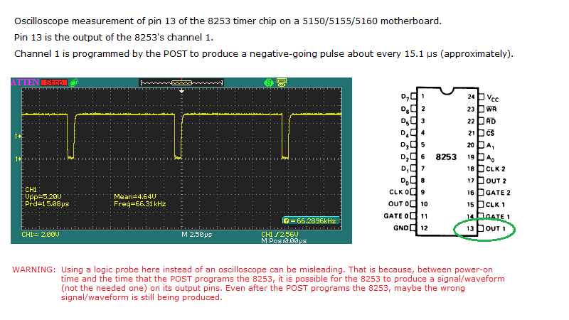
| 41 | Yes | Display "8253 timer channel 1" | ||
| 42 | Yes | Test 8253 timer channel 1. Mode 2 only. | If an error: 1. Send checkpoint 9B to [LPT1-3]+[COM1]+[IBMDIAG], 2. then halt. |
Halt beause with a failing timer 1, there won't be any refresh of motherboard and card RAM. That compromises a later test of that RAM. |
| 43 | Yes | Send checkpoint 1C to [LPT1-3]+[COM1]+[IBMDIAG] | ||
| 44 | Yes | Display "8253 timer channel 2" | ||
| 45 | Yes | Test 8253 timer channel 2. Mode 2 only. | If an error, send checkpoint 9C to [LPT1-3]+[COM1]+[IBMDIAG] | |
| 46 | Yes | Send checkpoint 1F to [LPT1-3]+[COM1]+[IBMDIAG] | ||
| 47 | Yes | Display "8237A DMA controller" | ||
| 48 | Yes | Test the 8237A DMA controller. | If an error: 1. Send checkpoint 9F to [LPT1-3]+[COM1]+[IBMDIAG], 2. then halt. |
|
| 48 | Yes | Send checkpoint 22 (hex) to [LPT1-3]+[COM1]+[IBMDIAG] | ||
| 50 | Yes | Configure the 8237 DMA controller | Includes preparing for RAM refresh by appropriately configuring channel 0. | |
| 51 | Yes | Send checkpoint 24 (hex) to [LPT1-3]+[COM1]+[IBMDIAG] | ||
| 52 | Yes | Display "Hot timer 1 check" | ||
| 53 | Yes | Look for a 'hot' timer 1' | If error, send checkpoint A5 to [LPT1-3]+[COM1]+[IBMDIAG] | The DREQ0 pin on the 8237A DMA controller is expected to be LOW. |
| 54 | Yes | Send checkpoint 26 (hex) to [LPT1-3]+[COM1]+[IBMDIAG] | ||
| 55 | Yes | Initialise channel 1 on the 8253 timer chip. | One pulse per approximately 15 µs. See here. | |
| 56 | Yes | Send checkpoint 28 (hex) to [LPT1-3]+[COM1]+[IBMDIAG] | ||
| 57 | Yes | Display "RAM parity error latches" | ||
| 58 | Yes | Step 1: Clear/disable the two 'RAM parity error' latches. Step 2: Verify that neither of the two latches are showing as set. |
If error, send checkpoint A7 to [LPT1-3]+[COM1]+[IBMDIAG] | |
| 59 | Yes | Send checkpoint 2A to [LPT1-3]+[COM1]+[IBMDIAG] | ||
| 60 | Yes | Display "Check first 2 KB of RAM" | ||
| 61 | Yes | Check the first 2 KB of RAM. | If an error: 1. Send checkpoint AA (hex) to [LPT1-3]+[COM1]+[IBMDIAG], 2. then display error details on-screen, 3. then send error details to [COM1], 4. then halt. |
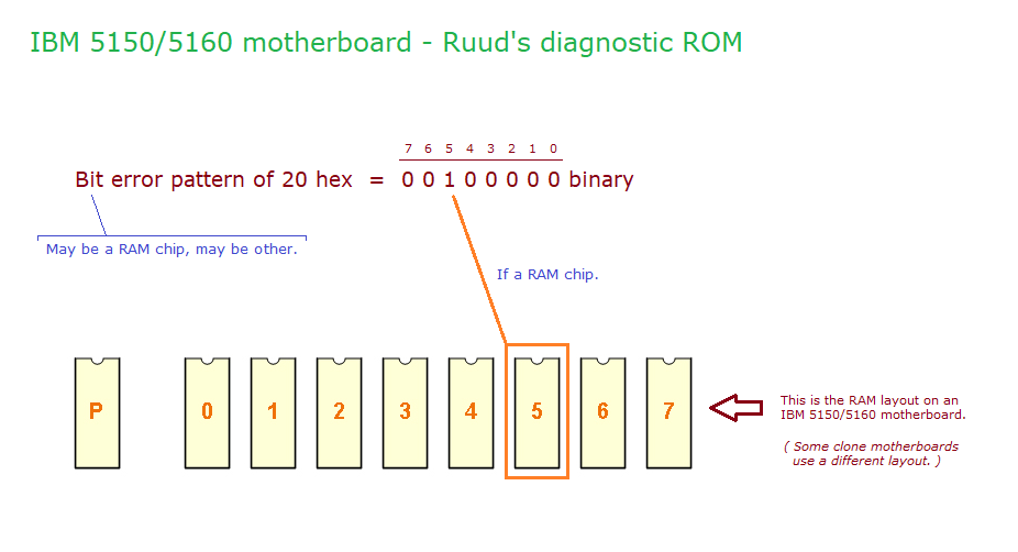
If an error: An RS-232 serial terminal (or terminal program) on COM1 will see something like 'AA 4000 20' In the example given, the '4000' is the failing address. In the example given, the '20' is the bit error pattern. 00 indicates the parity bit. |
| 62 | Yes | Send checkpoint 32 (hex) to [LPT1-3]+[COM1]+[IBMDIAG] | ||
| 63 | Yes | Display "Found RAM:" | ||
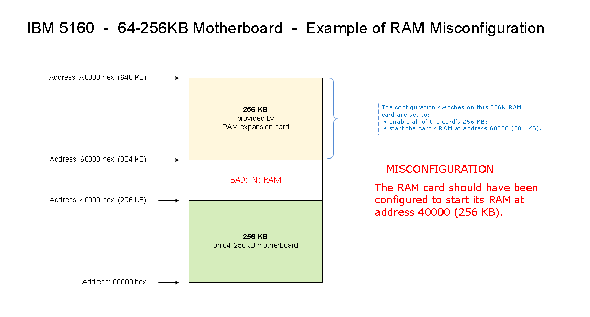
| 64 | Yes | See how much Conventional memory can be found. | Strickly speaking, what this diagnostic reports is the top address of RAM. For example, in the misconfiguration shown at here, the diagnostic will report 640 KB. Same if a RAM card goes faulty in a way that creates a gap between motherboard RAM and card RAM. |
|
| 65 | Yes | Send checkpoint 34 (hex) to [LPT1-3]+[COM1]+[IBMDIAG] | ||
| 66 | Yes | Display the amount of RAM found. | ||
| 67 | Yes | Send checkpoint 35 (hex) to [LPT1-3]+[COM1]+[IBMDIAG] | ||
| 68 | Yes | Display "Testing RAM - Data" | ||
| 69 | Yes | Do a data test of the found RAM. | If an error: 1. Send checkpoint B5 (hex) to [LPT1-3]+[COM1]+[IBMDIAG], 2. then display error details on-screen, 3. then send error details to [COM1], 4. then halt. |
If an error: An RS-232 serial terminal (or terminal program) on COM1 will see something like 'B5 4000 20' In the example given, the '4000' is the failing address. In the example given, the '20' is the bit error pattern. 00 indicates the parity bit. |
| 70 | Yes | Send checkpoint 37 (hex) to [LPT1-3]+[COM1]+[IBMDIAG] | ||
| 71 | Yes | Display "Testing RAM - Address" | ||
| 72 | Yes | Adddress test of the found RAM - Part 1 of 2. See here for a crude description of a memory addressing problem. |
If an error: 1. Send checkpoint B7 (hex) to [LPT1-3]+[COM1]+[IBMDIAG], 2. then display error details on-screen, 3. then send error details to [COM1], 4. then halt. |
If an error: An RS-232 serial terminal (or terminal program) on COM1 will see something like 'B7 4000 20' In the example given, the '4000' is the failing address. In the example given, the '20' is the bit error pattern. |
| Yes | Adddress test of the found RAM - Part 2 of 2. | If an error: 1. Send checkpoint B8 (hex) to [LPT1-3]+[COM1]+[IBMDIAG], 2. then display error details on-screen, 3. then send error details to [COM1], 4. then halt. |
If an error: An RS-232 serial terminal (or terminal program) on COM1 will see something like 'B8 4000 20' In the example given, the '4000' is the failing address. In the example given, the '20' is the bit error pattern. |
|
| 73 | Yes | Send checkpoint 39 (hex) to [LPT1-3]+[COM1]+[IBMDIAG] | ||
| 74 | Yes | Display "Testing RAM - Refresh" | ||
| 75 | Yes | Do a test of RAM refresh. | If an error: 1. Send checkpoint B9 (hex) to [LPT1-3]+[COM1]+[IBMDIAG], 2. then display error details on-screen, 3. then send error details to [COM1], 4. then halt. |
90 second delay between test write then read-back. A 90 second count-down will be seen on the screen. If an error: A serial terminal (or terminal program) on COM1 will see something like 'B9 4000' In the example given, the '4000' is the failing address. |
| 76 | Yes | Send checkpoint 3A to [LPT1-3]+[COM1]+[IBMDIAG] | ||
| 77 | Yes | Display "Testing RAM - Slow Refresh" | ||
| 78 | Yes | Test the RAM at the refresh rate of 2 milliseconds. | If an error: 1. Send checkpoint BA (hex) to [LPT1-3]+[COM1]+[IBMDIAG], 2. then display error details on-screen, 3. then send error details to [COM1], 4. then halt. |
If an error: An RS-232 serial terminal (or terminal program) on COM1 will see something like 'BA 4000 20' In the example given, the '4000' is the failing address. In the example given, the '20' is the bit error pattern. |
| 79 | Yes | Send checkpoint 3E to [LPT1-3]+[COM1]+[IBMDIAG] | ||
| 80 | Yes | Display "8259 interrupt controller" | ||
| 81 | Yes | Test the 8259 interrupt controller. | If an error, send checkpoint BE to [LPT1-3]+[COM1]+[IBMDIAG] | |
| 82 | Yes | Send checkpoint 40 (hex) to [LPT1-3]+[COM1]+[IBMDIAG] | ||
| 83 | Yes | Display "Hot IRQ interrupts". | ||
| 84 | Yes | Check if the 8259 sees an interrupt (IRQ0 to IRQ7) when one is unexpected. | If an interrupt, send checkpoint C0. | |
| 85 | Yes | Send checkpoint 42 (hex) to [LPT1-3]+[COM1]+[IBMDIAG] | ||
| 86 | Yes | Display "Checking interrupt IRQ0". | ||
| 87 | Yes | Verify correct operation of Interrupt 0. | If an error, send checkpoint C2 to [LPT1-3]+[COM1]+[IBMDIAG] | |
| 88 | Yes | Send checkpoint 46 (hex) to [LPT1-3]+[COM1]+[IBMDIAG] | ||
| 89 | Yes | Display "Hot NMI". | ||
| 90 | Yes | Verify that the 8088 CPU is not receiving an NMI. | If an error (NMI present), send checkpoint C6 to [LPT1-3]+[COM1]+[IBMDIAG] | |
| 91 | Yes | Send checkpoint 4E to [LPT1-3]+[COM1]+[IBMDIAG] | ||
| 92 | Yes | Display "Keyboard responds to reset". | ||
| 93 | Yes | Software reset the keyboard, and see if in response, the keyboard sends the expected byte of AA. | If an error, send checkpoint CE to [LPT1-3]+[COM1]+[IBMDIAG] | |
| 94 | Yes | Send checkpoint 50 (hex) to [LPT1-3]+[COM1]+[IBMDIAG] | ||
| 95 | Yes | Display "Keyboard stuck key". | ||
| 96 | Yes | See if the keyboard is reporting a stuck key. | If an error, send checkpoint D0 to [LPT1-3]+[COM1]+[IBMDIAG] | |
| 97 | Yes | Send checkpoint 52 (hex) to [LPT1-3]+[COM1]+[IBMDIAG] | ||
| 98 | Yes | Display "Check floppy controller". | ||
| 99 | Yes | See if a reset of the floppy controller is successful. | If an error, send checkpoint D2 to [LPT1-3]+[COM1]+[IBMDIAG] | |
| 100 | Yes | Send checkpoint 54 (hex) to [LPT1-3]+[COM1]+[IBMDIAG] | ||
| 101 | Yes | Display "Trying to read a floppy". | ||
| 101 | Yes | Try to read a track on a 360K floppy. | If an error, send checkpoint D4 to [LPT1-3]+[COM1]+[IBMDIAG] | 360K floppy drive required. |
| 102 | Yes | Send checkpoint 60 (hex) to [LPT1-3]+[COM1]+[IBMDIAG] | ||
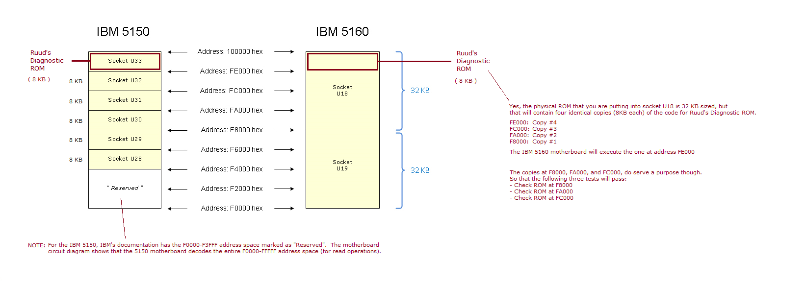
| 103 | Yes | Display "Check ROM at F4000". | IBM 5150: IC socket U28. IBM 5160: IC socket U19. Diagram at here. | |
| 104 | Yes | Verify that 8 KB at F4000 has an 8-bit checksum of 00. (Ignore result if no 8KB ROM at F4000 - may pass, may fail.) |
Ignore result if no 8KB ROM at F4000 - may pass, may fail. | |
| 105 | Yes | Send checkpoint 61 (hex) to [LPT1-3]+[COM1]+[IBMDIAG] | ||
| 106 | Yes | Display "Check ROM at F6000". | IBM 5150: IC socket U29. IBM 5160: IC socket U19. Diagram at here. | |
| 107 | Yes | Verify that 8 KB at F6000 has an 8-bit checksum of 00. (Ignore result if no 8KB ROM at F6000 - may pass, may fail.) |
Ignore result if no 8KB ROM at F6000 - may pass, may fail. | |
| 108 | Yes | Send checkpoint 62 (hex) to [LPT1-3]+[COM1]+[IBMDIAG] | ||
| 109 | Yes | Display "Check ROM at F8000". | IBM 5150: IC socket U30. IBM 5160: IC socket U18. Diagram at here. | |
| 110 | Yes | Verify that 8 KB at F8000 has an 8-bit checksum of 00. (Ignore result if no 8KB ROM at F8000 - may pass, may fail.) |
Ignore result if no 8KB ROM at F8000 - may pass, may fail. | |
| 111 | Yes | Send checkpoint 63 (hex) to [LPT1-3]+[COM1]+[IBMDIAG] | ||
| 112 | Yes | Display "Check ROM at FA000". | IBM 5150: IC socket U31. IBM 5160: IC socket U18. Diagram at here. | |
| 113 | Yes | Verify that 8 KB at FA000 has an 8-bit checksum of 00. (Ignore result if no 8KB ROM at FA000 - may pass, may fail.) |
Ignore result if no 8KB ROM at FA000 - may pass, may fail. | |
| 114 | Yes | Send checkpoint 64 (hex) to [LPT1-3]+[COM1]+[IBMDIAG] | ||
| 115 | Yes | Display "Check ROM at FC000". | IBM 5150: IC socket U32. IBM 5160: IC socket U18. Diagram at here. | |
| 116 | Yes | Verify that 8 KB at FC000 has an 8-bit checksum of 00. (Ignore result if no 8KB ROM at FC000 - may pass, may fail.) |
Ignore result if no 8KB ROM at FC000 - may pass, may fail. | |
| 117 | Yes | Send checkpoint 6A to [LPT1-3]+[COM1]+[IBMDIAG] | ||
| 118 | Yes | Display the switch setting | ||
| 119 | Yes | Send checkpoint 72 (hex) to [LPT1-3]+[COM1]+[IBMDIAG] | ||
| 120 | Yes | Update the 'Completed passes' figure | ||
| 121 | Yes | Send checkpoint 74 (hex) to [LPT1-3]+[COM1]+[IBMDIAG] |
| Note 1 | Possible problems in using 00 instead could be: • 00 might be the default power-on display of some parallel/LPT monitoring devices. • Some parallel/LPT monitoring devices may register a 00 (and other bytes) at power-on time. |
| Note 2 | Low RAM is untested at this point, but do it anyway. In fact, there may be no low RAM at all, but do it anyway. If the 'unxepected NMI' handler gets called, checkpoint 99 will be sent, and *** UNEXPECTED NMI *** be displayed on a MDA/CGA screen. |
| Note 3 | Yes, we are taking the chance that the circuitry involved in beeping the speaker is working. No beeps might be because: • No speaker connected to motherboard. • Diagnostic ROM not created properly. • Diagnostic ROM has started to execute, but circuitry involved in beeping the speaker is faulty. |