| Home |
| Step 1.1 | Power on the motherboard. |
| Step 1.2 | Wait for the 131 error to appear. <---- IMPORTANT (see note 1) |
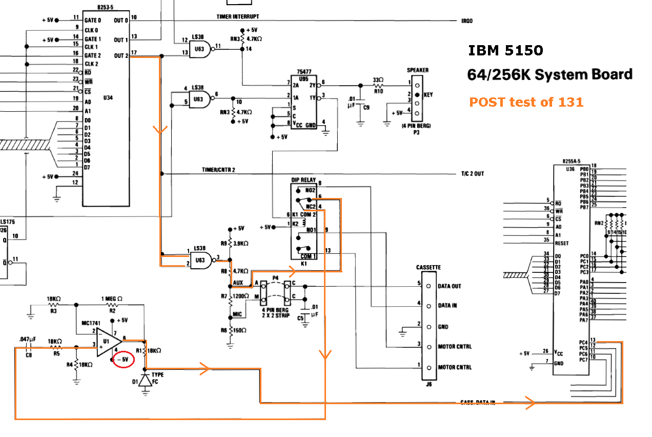
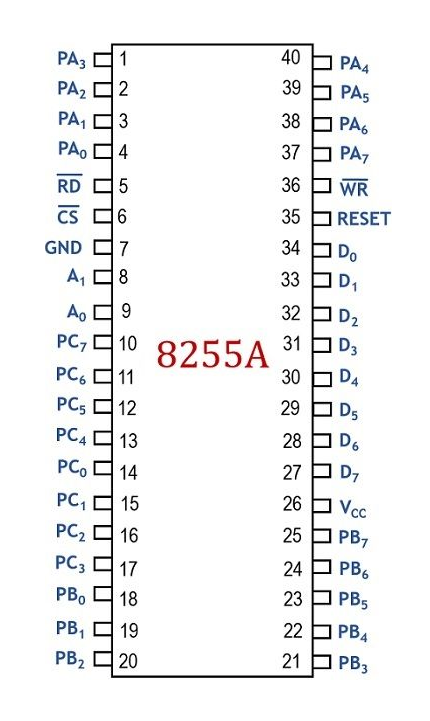
| Step 1.3 | Refer to the blue path in the diagram at here. Measure the DC voltage on pin 21 of chip U36 (the 8255A). See here for a pinout of the 8255A. If a TTL high (+2V to +5V), then proceed on to step 2. If not, either: • chip U36 (the 8255A) is faulty; or <-------------------------------------------------------- most likely of the three • chip U63 is faulty in a particular way, dragging down pin 21 of chip U36; or • a PCB problem. |
| Step 2.1 | Power on the motherboard. |
| Step 2.2 | Wait for the 131 error to appear. <---- IMPORTANT (see note 1) |
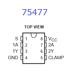
| Step 2.3 | Refer to the blue path in the diagram at here. Measure the DC voltage on pin 2 of chip U95, a 75477. See here for a pinout of the 75477. If a TTL low (0V to +0.8V), then proceed on to step 3. If not, either: • Chip U63 is faulty; or <-------------------------------------------------------- most likely of the three • Chip U95 is faulty in a particular way, dragging down pin 6 of chip U63; or • A PCB problem. |
| Step 3.1 | Power on the motherboard. |
| Step 3.2 | Wait for the 131 error to appear. <---- IMPORTANT (see note 1) |
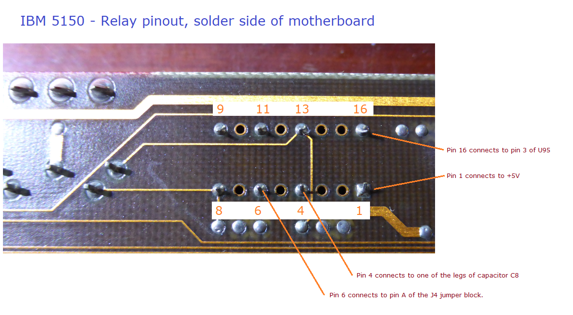
| Step 3.3 | Refer to the blue path in the diagram at here. Measure the DC voltage on pin 3 of chip U95, a 75477. See here for a pinout of the 75477. If about +5V, then proceed on to step 4. If not, either: • Chip U95 is faulty; or <-------------------------------------------------------- most likely of the two • A PCB problem, dragging down pin 3 of chip U95, turning the relay on. BTW. There are some other possibilities for not measuring about +5V, but they would not cause a 131 error: • The probes of your multimeter did not pierce the oxide layer on the pin/s of the chip. • Open-circuit between pin 3 of chip U95 and pin 16 of the relay (faulty trace or solder joint). |
| Note: | On pin 3 (an output pin) of the 75477, TTL high's and low's are not applicable. The inputs to the 75477 are TTL, but the output pins are not. Expected is that the 75477 is not pulling current though the relay's coil, and because of that, the voltage expected is whatever voltage is on the other side of the coil, namely +5V. |
| Step 4.1 | Power on the motherboard. |
| Step 4.2 | Wait for the 131 error to appear. <---- IMPORTANT (see note 1) |
| Step 4.3 | Refer to the pinout diagram of the relay at here. Measure the DC voltage on pin 16 of the relay. Approximately +5 volts is expected. |
| Note 1 | There is a delay before the POST programs/configures the 8253 chip to generate the tone for the 131 test, and turns off the relay. When you see the '131' on-screen, you know that the POST has done both. |